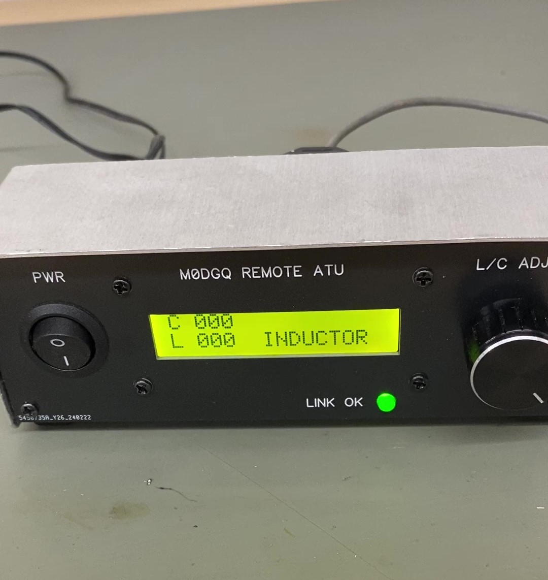
Described here is a simple remote located HF ATU. Its primary purpose is to feed/match a end fed long wire. The controller is located in my shack while the atu is located at the antenna feed point which is approximately fifty meters away at the bottom of my garden.I wanted to keep the feedpoint as far away from the house as possible to minimise any TVI.
Originally a endfed long wire was used with its feed point in the shack (which happens to be in the attic of the house) and a ground/counterpoise wire running down to a ground rod in the garden.Unfortunately TVI was an issue at high power levels, the relatively long counterpoise radiated on some of the shorter wavelengths. The feed point at the bottom of the garden is only two meters above ground so a very short ground wire can be used which produces a relatively efficient ground, whereas in the shack the ground wire was eight meters long.
Both the controller and the atu utilise a PIC16F628A as the processors. The atu is controled using RS232 generated from the controller. A one byte (256 bits) word is sent to the atu one initial power up and when the rotary encoder is incremented or decremented on the controller. The first 127 bits control the capacitor setting in the atu and bits 128 -254 control the inductor setting which form a L-match in the atu. The capacitor is incremented/decremented in a binary ladder fashion while the inductor is incremented/decremented in base 10 - see the demo. The first capacitor has a value of 10pF and every following capacitor is doubled, the final capacitor being 820pF thus the capacitance can be varied from 0 to 1640pF in 10pF steps.
In this controller, when inductor value 14 is selected a torroid rf transformer is placed in circuit in order to match my end fed (which is approximately one quater wavelength on top band) to top band, 1.8MHz. This is done purely in hardware with relays and does not have to be implemented if not needed. Aprroximately every three seconds the RS232 link integrity is checked using a timer0/counter interupt subroutine generated in the controller.
The ASM code used here is reasonably well comented so if you want to tinker with it (memories etc.) it should not be too dificult to figure out.
Here is a youtube link showing the atu in use DEMO
receiver schematic
controller schematic
Inside atu
Inside controller
atu asm code
controller asm code
Barry Zarucki M0DGQ
HOME